
The MIFETM
system
for non-invasive measurement of specific fluxes in solution
near living
plant or animal tissue

|
|
The MIFETM
system
| |
|
Home UTas Biophysics Lab MIFE user group Overview MIFE theory Hardware Software Purchasing |
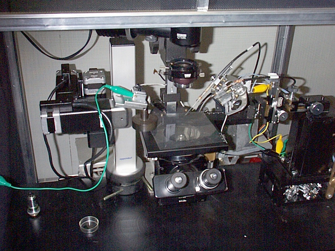
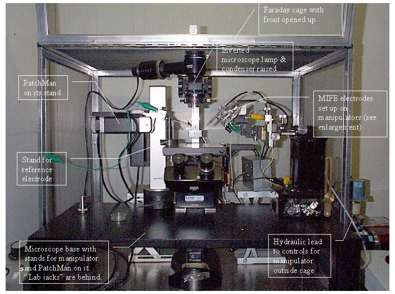
MIFE HardwareThe MIFE system uses a stepper motor-driven micromanipulator to move, in a "square wave", ion selective microelectrodes that measure the electrochemical potential of the ions at two positions in solution close to a tissue surface. The manipulator is obtained from a separate commercial source and a multi-electrode holder is needed if more than one ion is to be measured. Microsensors for neutral molecules may also be used. An amplifier, with 4-channel preamplifiers, provides the signals to the data acquisition card in a computer. The MIFE system will be used within a well equipped electrophysiology laboratory and a variety of other components (see below) are needed. The system can be used with the sample in a dish on an
inverted microscope. This configuration is shown in a general view showing the
MIFE hydraulic manipulator (outmoded version of the system) on the
right. For seedling roots it is more convenient to use a standard compound microscope lying on its back, with the root lying in a vertical chamber on the microscope stage, as shown in this picture (thanks to Trevor Garnett) of a Eucalyptus nitens root for which 3 fluxes are being measured. MIFE Hardware - System component summaryWell equipped electrophysiology lab with bench and Faraday cage.Microelectrode preparation and filling facilities. Microscope with vertical or horizontal optic axis as required for the application. MIFE custom-assembled Narishige manipulator system (SM-17, MHW-4, MX-2), with a MIFE stepper motor drive; or alternatively, Eppendorf PatchMan NP2 computer controlled micromanipulator. Multiple electrode mount in some cases. Manual micromanipulator for adjusting electrode or chamber position. Computer running Windows 98 or ME and having one ISA-bus slot (for the DAS08 card) with a spare slot beside it, with USB or network connection. MIFE electronics: main amplifier and two 4-channel preamplifiers. [supplied by UTas Research Office Commercialisation Unit] CHART/MIFEFLUX software. [supplied by UTas Research Office Commercialisation Unit] General purpose software including spreadsheet. MIFE laboratory requirements. Many other things are needed for to measure ion fluxes. We have provided an outline of these requirements with estimates of costs and sources of supply. Some additional descriptive details are given in the book chapter :- The MIFE setup is built around the microscope
system with long distance objectives (200 to 500x total magnification). There
are several basic configurations of the MIFE system used in our laboratory.
When fluxes are to be measured from small specimens (single cells; protoplasts;
bacterial monolayers etc), an inverted microscope is used. The ion-selective
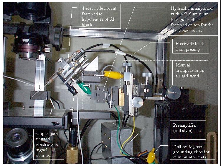
electrodes (usually, up to three) are mounted on a multi-manipulator providing
3- dimensional positioning. Typically, we use WI 64-0918 electrode holders (SDR
Clinical Technology, Middle Cove, Australia) held in a MMT-5 or SM-17 (Narishige, Tokyo,
Japan) micromanipulator. This allows fine positioning of the electrode tips
near the specimen surface. The MMT manipulator is attached to the stepper
motor-driven 3-dimensional hydraulic micromanipulator (Narishige WR-88 or MHW-3
models). This enables the square-wave electrode movement to measure the electrochemical potential of the
ions at two positions in solution close to a tissue surface. Additional
flexibility in electrode positioning is achieved by mounting the MMT-5/MHW-3
ensemble on a Narishige MX-2 mechanical micromanipulator. Instead of the MHW-3, the MHW-4 single-axis may be used. The measured specimen is immobilized
at the bottom of the open type experimental chamber. The chamber is placed on
the microscope stand, and electrode holders are positioned at an angle of 30 ° to the microscope stand plane. The standard
non-polarizing Ag/AgCl reference electrode is positioned in the chamber. The
electrodes oscillate (usually at 0.1 Hz), between two positions, close (usually
10-20 mm) and more distant (40-50 mm) from the cells, driven by the
computer-controlled stepper motor. The
voltage output from the electrodes is amplified by the MIFE electrometer and digitized
using an analogue-to-digital interface card (DAS 08, Computer Boards Inc., The DOS-based CHART ( Flux calculations are performed automatically by the MIFEFLUX software ( For ion flux measurements from root or leaf
surface, a more “user-friendly” arrangement is used. In this case, the MIFE
setup is built around the standard stereomicroscope. The microscope is rotated
by 90o, so that the optical axis is horizontal. The measuring
chamber is mounted on the computer-driven 3-dimensional hydraulics
micromanipulator, while microelectrodes are held by the MMT-5 manipulator.
Under such an arrangement, the electrodes are steady, and it is a slow movement
of the measuring chamber that enables flux measurement. The main advantage of
this arrangement is the convenience of electrode positioning (much further from
the chamber’s bottom – thus, less danger for electrodes to be broken). For more
details, refer to Shabala and Newman (1997).
|
Maintained by Ian Newman. Date . © University of Tasmania.